- Section 2: Configure and Administer Advanced vSphere 6.x Networking
Section 2: Configure and Administer Advanced vSphere 6.x Networking
Section 2 of the VCP6-DCV blueprint
Objective 2.1: Configure Advanced Policies/Features and Verify Network Virtualization Implementation
Create/Delete a vSphere Distributed Switch
- In the vSphere Web Client, navigate to a data center.
- In the navigator, right-click the data center and select Distributed Switch > New Distributed Switch.
- In Name and Location, type a name for the new distributed switch, or accept the generated name, and click Next.
- In Select version, select a distributed switch version and click Next.
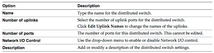
- In Edit Settings configure the distributed switch settings.
- Use the arrow buttons to select the Number of uplinks.
- Use the drop-down menu to enable or disable Network I/O Control.
- Select the Create a default port group check box to create a new distributed port group with default settings for this switch.
- (Optional) To create a default distributed port group, type the port group name in the Port group name, or accept the generated name.
- Click Next.
- In Ready to complete, review the settings you selected and click Finish.
Add/Remove ESXi Hosts from a vSphere Distributed Switch
- In the vSphere Web Client, navigate to the distributed switch.
- From the Actions menu, select Add and Manage Hosts.
- Select Add hosts and click Next.
- Click New hosts, select from the hosts in your data center, and click OK.
- Select the tasks for configuring network adapters to the distributed switch and click Next. Configure physical NICs on the distributed switch.
- From the On other switches/unclaimed list, select a physical NIC.
- Click Assign uplink.
- Select an uplink and click OK.
- Click Next.
- Configure VMkernel adapters.
- Select a VMkernel adapter and click Assign port group.
- Select a distributed port group and click OK.
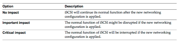
- Review the impacted services as well as the level of impact.
- Click Next.
- Configure virtual machine networking.
- To connect all network adapters of a virtual machine to a distributed port group, select the virtual machine, or select an individual network adapter to connect only that adapter.
- Click Assign port group.
- Select a distributed port group from the list and click OK.
- Click Next and click Finish.
Add/Configure/Remove dvPort groups
- In the vSphere Web Client, navigate to the distributed switch.
- Right-click the distributed switch and select Distributed port group > New distributed port group.
- In the Select name and location section, type the name of the new distributed port group, or accept the generated name, and click Next.
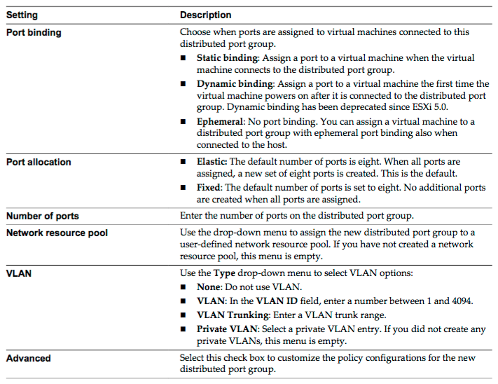
- In the Configure settings section, set the general properties for the new distributed port group and click Next.
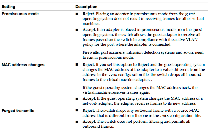
- (Optional) In the Security section, edit the security exceptions and click Next.
Add/Remove uplink adapters to dvUplink groups
- In the vSphere Web Client, navigate to the distributed switch.
- From the Actions menu, select Add and Manage Hosts.
- Select Manage host networking and click Next.
- Click Attached hosts and select from the hosts that are associated with the distributed switch.
- Click Next.
- Select Manage physical adapters and click Next.
- From the On other switches/unclaimed list select a physical NIC .
- Click Assign uplink.
- Select an uplink or select Auto-assign.
- Click Next.
- Review the impacted services as well as the level of impact.
- Click Next and click Finish.
Configure vSphere Distributed Switch general and - dvPort group settings
- In the vSphere Web Client, navigate to the distributed switch. Click Manage tab, click Settings, and select Properties.
- Click Edit.
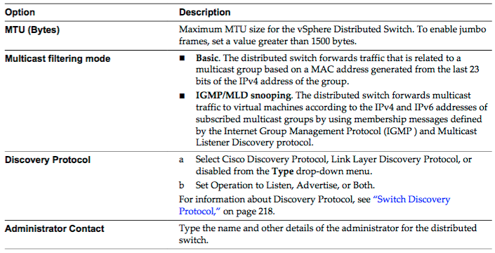
- Click General to edit the vSphere Distributed Switch settings.
- Click Advanced to edit the vSphere Distributed Switch settings.
- Click OK.
Create/Configure/Remove virtual adapters
- In the vSphere Web Client, navigate to the distributed switch.
- From the Actions menu, select Add and Manage Hosts.
- Select Manage host networking and click Next.
- Click Attached hosts and select from the hosts that are associated with the distributed switch. Click Next.
- Select Manage VMkernel adapters and click Next.
- Click New adapter.
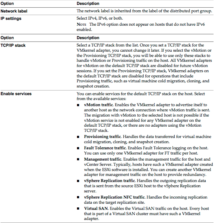
- On the Select target device page of the Add Networking wizard, select a distributed port group. On the Port properties page, configure the settings for the VMkernel adapter.
- If you selected the vMotion TCP/IP or the Provisioning stack, click OK in the warning dialog that appears.
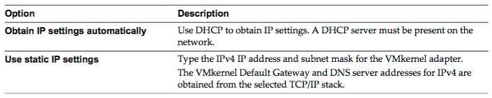
- (Optional) On the IPv4 settings page, select an option for obtaining IP addresses.
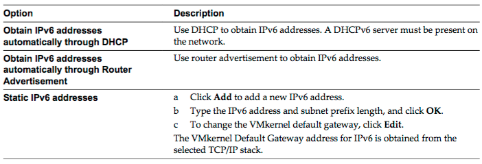
- (Optional) On the IPv6 settings page, select an option for obtaining IPv6 addresses.
- Review your setting selections in the Ready to complete page and click Finish.
- Follow the prompts to complete the wizard.
Migrate virtual machines to/from a vSphere Distributed Switch
- In the vSphere Web Client, navigate to the distributed switch.
- From the Actions menu, select Add and Manage Hosts.
- Select Manage host networking and click Next.
- Click Attached hosts and select from the hosts that are associated with the distributed switch. Click Next.
- Select Migrate virtual machine networking and click Next.
- Configure virtual machine network adapters to the distributed switch.
- To connect all network adapters of a virtual machine to a distributed port group, select the virtual machine, or select an individual network adapter to connect only that adapter.
- Click Assign port group.
- Select a distributed port group from the list and click OK.
- Click Next and click Finish.
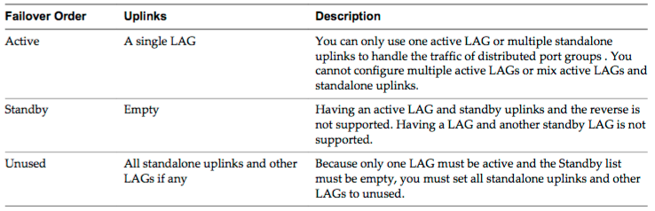
Configure LACP on vDS given design parameters
- You configure a LAG with two or more ports and connect physical NICs to the ports. LAG ports are teamed within the LAG, and the network traffic is load balanced between the ports through an LACP hashing algorithm. You can use a LAG to handle the traffic of distributed port groups to provide increased network bandwidth, redundancy, and load balancing to the port groups.
- When you create a LAG on a distributed switch, a LAG object is also created on the proxy switch of every host that is connected to the distributed switch. For example, if you create LAG1 with two ports, LAG1 with the same number of ports is created on every host that is connected to the distributed switch.
- On a host proxy switch, you can connect one physical NIC to only one LAG port. On the distributed switch, one LAG port can have multiple physical NICs from different hosts connected to it. The physical NICs on a host that you connect to the LAG ports must be connected to links that participate in an LACP port channel on the physical switch.
- You can create up to 64 LAGs on a distributed switch. A host can support up to 32 LAGs. However, the number of LAGs that you can actually use depends on the capabilities of the underlying physical environment and the topology of the virtual network. For example, if the physical switch supports up to four ports in an LACP port channel, you can connect up to four physical NICs per host to a LAG.
Describe vDS Security Polices/Settings
- In the vSphere Web Client, navigate to the distributed switch.
- Navigate to the Security policy for the distributed port group or port.
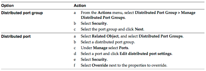
- Reject or accept promiscuous mode activation or MAC address changes in the guest operating system of the virtual machines attached to the distributed port group or port.
- Review your settings and apply the configuration.
Configure dvPort group blocking policies
- In the vSphere Web Client, navigate to the distributed switch.
- Right-click the distributed switch in the object navigator and select Distributed Port Group > Manage Distributed Port Groups.
- Select the Miscellaneous check box and click Next.
- Select one or more distributed port group to configure and click Next.
- From the Block all ports drop-down menu, enable or disable port blocking, and click Next.
- Review your settings and click Finish.
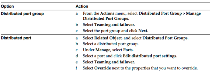
Configure load balancing and failover policies
- In the vSphere Web Client, navigate to the distributed switch.
- Navigate the Teaming and Failover policy on the distributed port group or port.
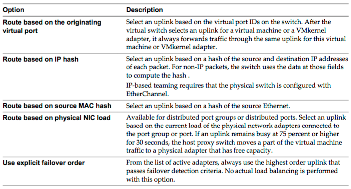
- From the Load Balancing drop-down menu, specify how the virtual switch load balances the outgoing traffic between the physical NICs in a team.
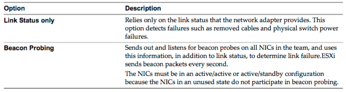
- From the Network Failover Detection drop-down menu, select the method that the virtual switch uses for failover detection.
- From the Notify Switches drop-down menu, select whether the standard or distributed switch notifies the physical switch in case of a failover.
- From the Failback drop-down menu, select whether a physical adapter is returned to active status after recovering from a failure.
- If failback is set to Yes, the default selection, the adapter is returned to active duty immediately upon recovery, displacing the standby adapter that took over its slot, if any.
- If failback is set to No for a distributed port, a failed adapter is left inactive after recovery only if the associated virtual machine is running. When the Failback option is No and a virtual machine is powered off, if all active physical adapters fail and then one of them recovers, the virtual NIC is connected to the recovered adapter instead of to a standby one after the virtual machine is powered on. Powering a virtual machine off and then on leads to reconnecting the virtual NIC to a distributed port. The distributed switch considers the port as newly added, and assigns it the default uplink port, that is, the active uplink adapter.
- If failback is set to Yes, the default selection, the adapter is returned to active duty immediately upon recovery, displacing the standby adapter that took over its slot, if any.
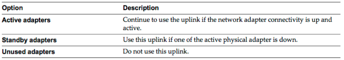
- Specify how the uplinks in a team are used when a failover occurs by configuring the Failover Order list.
- If you want to use some uplinks but reserve others for emergencies in case the uplinks in use fail, use the up and down arrow keys to move uplinks into different groups.
- Review your settings and apply the configuration.
Configure VLAN/PVLAN settings for VM’s given communication requirements
- A private VLAN is identified by its primary VLAN ID. A primary VLAN ID can have multiple secondary VLAN IDs associated with it. Primary VLANs are Promiscuous, so that ports on a private VLAN can communicate with ports configured as the primary VLAN. Ports on a secondary VLAN can be either Isolated, communicating only with promiscuous ports, or Community, communicating with both promiscuous ports and other ports on the same secondary VLAN.
- In the vSphere Web Client, navigate to the distributed switch.
- On the Manage tab, click Settings.
- Select Private VLAN and click Edit.
- To add a primary VLAN, under Primary VLAN ID click Add and enter the ID of a primary VLAN. Click the plus sign (+) in front of the primary VLAN ID to add it to the list.
- To add a secondary VLAN, in the right pane click Add and enter the ID of the VLAN. Click the plus sign (+) in front of the secondary VLAN ID to add it to the list.
- From the drop-down menu in the Secondary VLAN type column, select either Isolated or Community.
- Click OK.
Configure traffic shaping policies
- In the vSphere Web Client, navigate to the distributed switch.
- Navigate to the Traffic Shaping policy for the distributed port group or port.
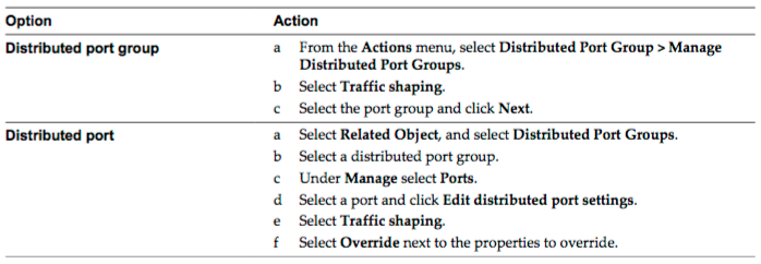
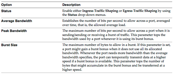
- Configure traffic shaping policies.
- Review your settings and apply the configuration.
Enable TCP Segmentation Offload support for a virtual machine
Enable Jumbo Frames support on appropriate components
Recognize behavior of vDS Auto-Rollback
Configure vDS across multiple vCenter Servers to support [Long Distance vMotion]
Compare and contrast vSphere Distributed Switch (vDS) capabilities
Objective 2.2: Configure Network I/O Control (NIOC)
- Define NIOC
- Explain NIOC capabilities
- Configure NIOC shares/limits based on VM requirements
- Explain the behavior of a given NIOC setting
- Determine Network I/O Control requirements
- Differentiate Network I/O Control capabilities
- Enable/Disable Network I/O Control
- Monitor Network I/O Control
Check out another blueprint section
- Section 1: Configure and Administer vSphere 6.x Security
- Section 2: Configure and Administer Advanced vSphere 6.x Networking
- Section 3: Configure and Administer Advanced vSphere 6.x Storage
- Section 4: Upgrade a vSphere Deployment to 6.x
- Section 5: Administer and Manage vSphere 6.x Resources
- Section 6: Backup and Recover a vSphere Deployment
- Section 7: Troubleshoot a vSphere Deployment
- Section 8: Deploy and Consolidate vSphere Data Center
- Section 9: Configure and Administer vSphere Availability Solutions
- Section 10: Administer and Manage vSphere Virtual Machines